

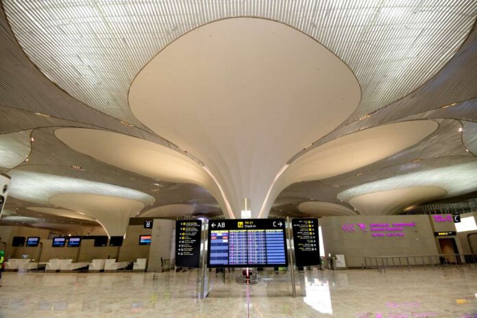
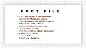
Introduction: The Navi Mumbai International Airport is one of India’s most ambitious infrastructure projects, a lotus-inspired, organically formed aviation hub that pushes the boundaries of what structural steel can achieve. Developed as a major greenfield aviation hub to decongest Mumbai’s existing airport, the terminal was delivered by Larsen & Toubro Construction through a hybrid RCC-steel approach, with detailed engineering by L&T EDRC. With approximately 13,000 MT of structural steel enabling complex organic forms, twisted 3D arch trusses spanning up to 113 metres, and tree-like mega columns of extraordinary scale, NMIA establishes a new benchmark in terminal architecture and structural engineering.
FORM INTO STRUCTURE
The biggest challenge was converting an architecturally driven free-form geometry into a practical and efficient structural steel system without compromising the design intent. The lotus-inspired roof comprises highly complex organic forms, large-span twisted arches, tree-like articulated columns, and multiple layers of secondary and tertiary steel supporting the architectural envelope. Achieving structural efficiency while maintaining the fluid architectural expression required extensive parametric modelling, advanced structural analysis, and continuous coordination between architecture, engineering, fabrication, and construction teams throughout every stage of design and execution.
A hierarchical structural system was adopted, comprising primary, secondary, and tertiary steel frameworks. The primary steel system carries the major structural loads, while the secondary and tertiary systems support the complex roof, cladding, skylights, bullnose elements, earmuffs, and other architectural features. By carefully defining load paths and ensuring that each structural layer served a specific purpose, the team was able to preserve the architectural vision while maintaining structural efficiency, constructability, and material optimisation.
“Achieving structural efficiency while maintaining the fluid architectural expression required extensive parametric modelling, advanced structural analysis, and continuous coordination between architecture, engineering, fabrication, and construction teams.”
THE TWISTED ARCH
The twisted 3D arch trusses spanning approximately 113 metres demanded the highest level of engineering ingenuity of any element in the terminal. Unlike conventional trusses, these members are curved in plan and twisted along their length while carrying significant gravity, wind, seismic, and cladding loads. Their behaviour could not be simplified into conventional load paths, requiring sophisticated three-dimensional analysis, detailed connection design, and carefully planned erection methodologies.
The interface between these arches, the tree-like mega columns, and the large-span secondary trusses added a further layer of complexity, particularly in controlling force transfer, fabrication tolerances, and construction-stage behaviour. Tree-like columns weighing up to approximately 130 MT, with dimensions varying from about 1 metre at the base to nearly 22 metres across the crown, were assembled at ground level and erected as single units. Large roof modules were similarly preassembled to maximise quality and minimise work at height. Temporary loading conditions, lifting forces, stability during intermediate construction stages, and crane capacities were all considered during structural design and detailing, erection engineering integrated into the design process from the very outset.
“The tree-like columns, weighing up to 130 MT and spanning nearly 22 metres across the crown, were assembled at ground level and erected as single units, erection engineering integrated into design from the very outset.”
Meticulous planning and coordination across all stakeholders, on a common design platform, was what made this extraordinary feat of execution possible. At 13 per cent of the overall built-up area, the transfer girder zone represents the most critical and challenging component of the entire project, one that would have been quite challenging to realise through conventional construction methods.
“It would be quite challenging to design such large span floors in conventional methods; the transfer girder is not just challenging in design, but also in fabrication and execution.”
THIRTEEN MEMBERS, ONE NODE
The most demanding aspect of the entire project was managing the critical interfaces within the structural system and nowhere was this more acute than at the complex box-node connections where up to thirteen structural members converged into a single node. These locations were required to transfer very large forces while simultaneously accommodating construction tolerances, temperature effects, differential movements, and erection-stage loading conditions. The architectural geometry demanded exceptional precision and visual continuity at the very same points where the structural complexity was greatest.
The three-dimensional nature of the structure meant that multiple members converged at highly complex nodes and connection regions, amplifying every challenge. Achieving the intended architectural appearance while maintaining structural integrity, constructability, and erection accuracy required extensive analysis, innovative connection detailing, and close coordination between concrete, steel, fabrication, and construction teams. In many respects, the success of these interfaces was fundamental to the successful realisation of the entire terminal structure.
One defining moment crystallised the achievement: the successful erection and alignment of the large-span twisted arch systems and articulated mega columns within specified tolerances, watching the complex geometry emerge exactly as envisioned, validating years of design development, digital coordination, fabrication control, and site engineering.
“The successful implementation of highly complex box-node connections, where up to thirteen structural members converged into a single node, was one of the defining milestones of this project.”
DIGITAL AT EVERY STAGE
Digital engineering formed the backbone of the project delivery strategy. STAAD.Pro was used for advanced structural analysis, while Tekla enabled highly detailed modelling of every member, connection, and fabrication interface. BIM 360 served as the common data environment, enabling seamless coordination among multidisciplinary teams. Laser scanning and point-cloud verification were extensively used during construction, scanned data continuously compared with the design model to identify deviations early and ensure erection accuracy across a structure with very few repetitive elements.
Nearly every major node, connection, and supporting element incorporated some degree of geometric variation. Complex assemblies were fabricated, trial-fitted, and validated under factory-controlled conditions before being transported to site. The ability to preassemble large modules reduced site welding, improved safety, accelerated erection, and enhanced dimensional accuracy, steel providing the flexibility necessary to accommodate complex architectural forms while ensuring construction efficiency, quality assurance, and schedule certainty.
“For projects of this complexity, success depends on integrating design, detailing, fabrication, quality assurance, and erection planning into a single collaborative workflow, digital coordination must remain seamless from design through fabrication and construction.” – DR. SREENATH S, Senior Lead Engineering Manager – Structural, EDRC, Larsen & Toubro Limited