

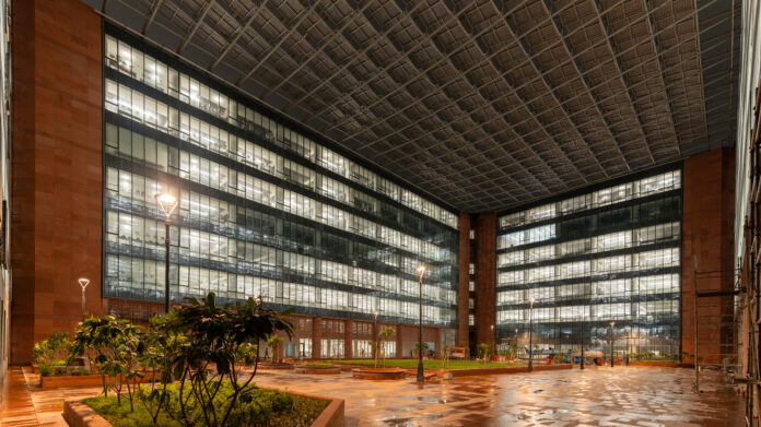
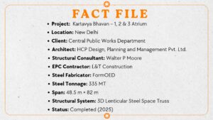
Introduction: The Kartavya Bhavan 1, 2 and 3 Atrium Structure in New Delhi is a landmark steel canopy spanning 48.5 m × 82 m over the civic courtyard of the Common Central Secretariat complex on Kartavya Path. 1, 2 and 3 Atrium Structure in New Delhi comprises a steel canopy measuring 48.5 m × 82 m over the civic courtyard of the Common Central Secretariat complex on Kartavya Path. Its engineering integrates lenticular trusses for long-span stiffness, bearings that accommodate relative movement between four supporting buildings, and modular fabrication for controlled site assembly.
A ROOF RECONSIDERED
The original architectural vision for the Kartavya Bhavan atrium was a visually transparent 3D cable-net roof spanning the central courtyard, cables running bidirectionally across top and bottom layers separated by vertical posts, with inclined perforated aluminium shading panels attached to create a light, floating canopy while maintaining daylight and ventilation.
The proposed structural scheme comprised four large perimeter box trusses supported on the surrounding buildings and supporting the bidirectional cable-net. To maintain stability under all load cases, including wind uplift, the cables had to remain in tension, requiring substantial pre-tension. These forces were transferred through the perimeter box trusses, base plates and bearings to the terrace levels of the supporting buildings. Increasing cable tension to control deflections therefore had implications beyond the cable-net itself: it required larger box trusses and member sizes, higher-capacity bearings, and more robust support interfaces.
The turning point came during the project cost evaluation, when HCP Design and the client’s team assessed the cable-net scheme against the tender budget and found that its estimated cost substantially exceeded the available allowance. Drawing on its experience in cable structures, Walter P Moore was appointed to review the atrium design and develop more economical alternatives while preserving the architectural intent. The review highlighted a fundamental trade-off: the higher cable tension needed to control displacement and maintain stability also increased demands on the cables, perimeter box trusses, connections, bearings and support interfaces, driving up both cost and construction complexity.
Three alternatives were developed within the project budget: two hybrid steel-and-cable options and one all-steel option. The client and HCP Design selected the lenticular steel truss system for its balance of economy, procurement, erection methodology and architectural compatibility. The decision reflected the project’s particular support conditions and delivery requirements.
The comparison concerned the complete structural system, not simply the members spanning the courtyard. Perimeter steelwork, support reactions and interfaces with the buildings were part of the same decision. For this project, economy therefore depended on how each option combined the spanning structure with its supports and construction requirements.
” The selected solution preserved the architectural intent while aligning structural performance with the project’s budget and construction requirements”
THE LENTICULAR LOGIC
The key insight that led to the lenticular steel truss came from reframing the challenge. The question was no longer how to make the cable-net work, it was how to preserve the architectural intent within the budget using a more efficient structural system. In the cable-net scheme, stability depended on pre-tension. But increasing tension increased demand on cables, box trusses, bearings, and terrace-level interfaces. The team therefore explored alternatives where stability came from structural form and member action rather than externally imposed pre-tension. The lenticular steel truss changed the structural logic most clearly. Instead of stabilising a flexible net through high cable forces, it used geometry to follow the natural force path. The truss becomes deepest at mid-span, where bending demand is highest, and tapers towards the supports, where bending demand reduces.
Steel is therefore placed precisely where it contributes most to structural efficiency, rather than maintaining unnecessary depth across the entire span. As a result, the roof did not need to borrow stability from the buildings it rested upon, did not need cables to maintain tension, prestress to control displacement, or anchorage into the host structures to remain stable. The primary structural system consists of lenticular steel trusses spanning the shorter courtyard direction of approximately 48.5 m, braced at top and bottom chords by secondary steel elements in the longitudinal direction of approximately 82 m, forming a complete three-dimensional space truss system of exceptional stiffness and redundancy. All primary and secondary steel members are fabricated from FE355 grade steel, Circular Hollow Sections for the truss and Rectangular Hollow Sections for perimeter beams.
Circular hollow sections were selected for their high torsional efficiency, uniform stress distribution under multi-directional loading, and refined visual expression, a quality that carries particular weight in a precinct of this national significance. Compared directly against the cable-net scheme, the lenticular steel truss was more predictable, more inspectable, and more constructible. Where the cable-net relied on pre-tension and anchorage to remain stable and drew large forces into the perimeter box trusses and supporting building interfaces, the lenticular system resolved forces through a clear, self-stable load path. The behaviour was conventional in the best sense, traceable, verifiable, and fully within the control of the engineering team at every stage.
“The lenticular form aligned structural depth with demand, integrating long-span efficiency with the architectural geometry”
THE BEARING STRATEGY
Perhaps the most elegant and consequential engineering decision in the project was the bearing strategy, a system that simultaneously allowed four independently moving RC buildings to behave as they naturally would, while giving the atrium roof a deliberate and controlled path for transferring lateral loads. The four surrounding buildings are separated by expansion joints and do not behave as one structure. Under temperature changes, creep, shrinkage, and seismic actions, each building can move independently. Had the atrium roof been rigidly connected, those relative movements would have generated unintended forces within both the roof and the buildings.
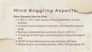 The design philosophy was therefore to treat the roof as an independent bridge-like structure supported on bearings, allowing each building to move without dragging the roof with it. This protected both the atrium structure and the host buildings simultaneously. The support system comprises 36 bi-directional roller bearings, 23 X-pinned uni-directional bearings, and 13 Y-pinned uni-directional bearings, distributed strategically around the perimeter. The bi-directional bearings allow the roof to slide in both X and Y directions, accommodating thermal movement, seismic displacement, and relative movement between buildings.
The X-pinned bearings restrain the roof in the X direction while allowing movement in Y. The Y-pinned bearings do the reverse. This arrangement prevents unwanted restraint forces from accumulating across all four buildings, but does not leave the roof laterally uncontrolled. The lateral load path is intentionally defined. All X-direction lateral forces, seismic forces and wind loads projected onto the inclined perforated panels, are transferred to one designated building line, and all Y-direction lateral forces to another. The remaining support lines slide under those lateral actions and do not attract unintended forces from the roof.
At the same time, all four building supports continue to resist gravity loads and wind uplift. The system separates vertical and uplift resistance from horizontal restraint, a distinction that proved essential to both the structural safety and the long-term independence of the roof. Some bearings were designed for movements approaching ±300 mm when building movement and roof displacement envelopes are combined, a figure that underscores just how much physical accommodation the system was engineered to provide. The remarkable aspect is not merely the magnitude of movement accommodated, but that the system simultaneously managed gravity loads, uplift, thermal movement, seismic displacement, and a controlled lateral load path, all within one compact bearing interface distributed around the perimeter of the roof.
“Movement where movement is required, restraint only where intended, and uplift safety maintained across all four buildings throughout.”
DESIGNED FOR DELHI’S EXTREMES
The structure was designed to the full rigour of Indian standards. Wind design adopted IS 875 (Part 3): 2015, with a regional basic wind speed of 50 m/s, terrain category 1, and a design wind speed of 63.45 m/s, yielding a design wind pressure of 1.45 kN/m² on the perforated aluminium shading panels, accounting for 50 per cent panel perforation and a conservative 75 per cent wind load retention. Seismic design per IS 1893: 2016 adopted Seismic Zone IV with an importance factor of 1.5 and a seismic coefficient of 0.45, a notably conservative approach given the civic significance of the structure.
Temperature loads spanning +20°C to −30°C were also incorporated. The perforated aluminium shading panels, inclined at 17° and sized at 3.325 m × 3.325 m, are engineered to intercept direct solar ingress into the work halls and reduce glare within the courtyard, substantially mitigating harsh Delhi summer conditions. Additional sustainable measures integrated into the broader complex include on-site solar energy generation, rainwater harvesting, wastewater management, and automated solid-waste management, collectively improving the microclimate and environmental performance of the precinct.
FABRICATION AND ERECTION
The construction strategy followed the same logic as the design: keep the system clear, modular, and controllable. The lenticular trusses were fabricated as transportable steel modules using hollow sections, with shop fabrication in Ahmedabad maintaining quality, geometry, and connection accuracy before components reached the site. The modules were transported to New Delhi and assembled using a predominantly bolted strategy, reducing dependence on extensive site welding, limiting temporary works, and enabling erection over an active central atrium condition coordinated with four supporting buildings.
During erection, actual deflections were measured and checked against predicted displacement values. The recorded deflections were equal to or lower than expected, confirming that the analytical model, fabrication geometry, erection control, and temporary stability assumptions were fully aligned with actual site behaviour. This alignment between prediction and performance was not incidental, it was the direct result of modular shop fabrication under controlled conditions, careful geometry control during assembly, and a bearing strategy that gave the structure the freedom to behave exactly as the analysis intended.
The final all-steel system weight of approximately 335 MT was the most material-efficient of the three structural options evaluated, including hybrid cable-steel and full cable-net alternatives. That efficiency was not the result of one feature alone. It came from aligning member geometry, spatial bracing, and bearing behaviour into one coherent structural system. The lenticular form contributed most directly, but its efficiency was fully realised only because the support and bearing strategy allowed the roof to move, restrain, and transfer forces in precisely the intended directions. If forced to identify the main contributor, it would be the lenticular form, but its efficiency was complete only because the entire system around it was designed to let it perform as intended.
“Our role as engineers is to understand the design intent, return to fundamentals, and select the system best suited to deliver that intent.” – AMOL ACHARYA, Principal and Director, Structural Engineering, Walter P Moore