

In addition to the benefits of high construction efficiency, good construction quality, and sustainable development associated with prefabricated steel structures, deconstructable steel structure systems enable quick disassembly and reuse of structural members following the completion of the structure. Deconstructable steel systems, therefore have greater promise in the engineering field. The splice joint is made of a lower square steel tubular column, an upper column, four numbers of splice plates and a number of high-strength bolts. The usage of high-strength bolts gives higher strength than regular bolts. High-strength bolts are made of some alloy steel. These bolts ensure that the structure remains safe even under harsh weather. The splice plates are designed as four numbers of independent plates to make sure that the splice plates well fit into the four other component plates of the column. Steel tubular constructions with distinct advantages are being employed more frequently as long-span skyscrapers and high-rise buildings continue to emerge.
Deconstructable structural design also refers to the use of reusable materials in the design stage to create structural components that are simple to assemble and disassemble. At present the research on deconstructable steel structure systems is very limited. While closed-section column-to-column splicing joints frequently use fully welded connections, which can’t satisfy the requirements of convenient disassembly, the majority of the column-to-column joints use fully bolted connections.
The current study proposes square and elliptical cross-sections of steel tubular columns with conventional high-strength bolts to realise the deconstructable connection of closed-section steel column splicing joints. A 3D finite element model was built using Ansys Workbench 2022 R2 software and further validated against the experiments, which may serve as an important reference for its use in real-world engineering applications. Non-linear analysis is being conducted. In cyclic loading tests, the bending moment rotation curves were obtained. Axial loadings were given to square and elliptical column sections and corresponding ultimate load and deflection curves were plotted.

VALIDATION
Cyclic loading is being tested for validation. The material properties and dimensions for validation are taken as shown below.
Material properties of 14 mm steel plate
Young’s modulus: 219,000 MPa
Poisson’s ratio: 0.3
Friction coefficient: 0.4
Yield strength: 385.2 MPa
Material properties of 10 mm steel column
Young’s modulus: 210000 MPa
Poisson’s ratio: 0.3
Yield strength: 405.2 MPa
The specimen chosen for validation was a splice connection in a square steel tubular column with splice plates being exactly placed in the middle position. The square steel tubular column of size 2245 mm x 220 mm x 10 mm is taken for validation.
High strength type of bolt is chosen with a nominal diameter M24, 10.9 grade bolt and the total number of bolts is 64. The splice plate of size 785 mm x 168 mm x 14mm is used. For cyclic testing bottom is fixed. At the top degrees of freedom in the vertical direction and rotation direction in the bending plane are released. The element type used is SOLID 186 (steel plates). Adaptive meshing is used for modelling. Connector elements BEAM 188 (Bolt) are used for modelling bolts. Hence bolts are modelled as 1D beam elements. Element size is 12 mm. The element shape of meshing is HEXAHERDON with a higher order element of 20 nodes. Total deformation, equivalent plastic strain and directional deformation are obtained after analysis using ANSYS workbench 2022 R2.
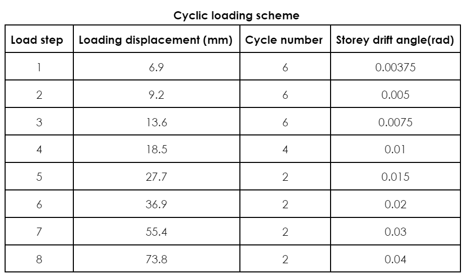
2.1 Cyclic loading
Loading is applied as per FEMA protocol. As per this protocol, 0.375% of drift is given first. Above 2-4 % if a structure withstands the load without fail, then the structure is said to be seismically best suited. Hence there is no need to test above 4%. Loading Height = 6.9 / 0.00375 = 1840 mm
Effect of axial loading
The square steel tubular column with a deconstructable splice joint modelled for validation is chosen and tested for axial loading by considering four parameters namely splice thickness, splice length, bolt diameter and bolt pattern. The boundary condition adopted is at the top axial load applied and the bottom is hinged. Under each parametric study load v/s deflection curve is obtained and studied their failure pattern.
Splice plate of thickness 14 mm, 12 mm, 10 mm, 8 mm and 6 mm are varied and tested. Splice plate of length 785 mm, 685 mm and 585 mm are tested under axial loading. Bolt diameters are varied from 24 mm, 22 mm, 20 mm, 18 mm and 16 mm. Bolt pattern is varied with 64, 48 and 32 numbers of bolts.
Similar to the square steel tubular column with a deconstructable splice joint, axial testing is done for an elliptical cross-section considering the four parameters namely splice thickness, splice length, bolt diameter and bolt pattern.
Modelling of elliptical steel tubular column
An elliptical steel tubular column with a deconstructable splice joint is modelled using a square steel tubular as the base model. The area of steel is 8424 mm2. Hence, the major axis of the elliptical column is 34 0mm and the minor axis is 200 mm. Material properties of the elliptical column and splice plate are similar to square steel tubular column. Modelling is done using ANSYS Design Modeler.
Conclusion
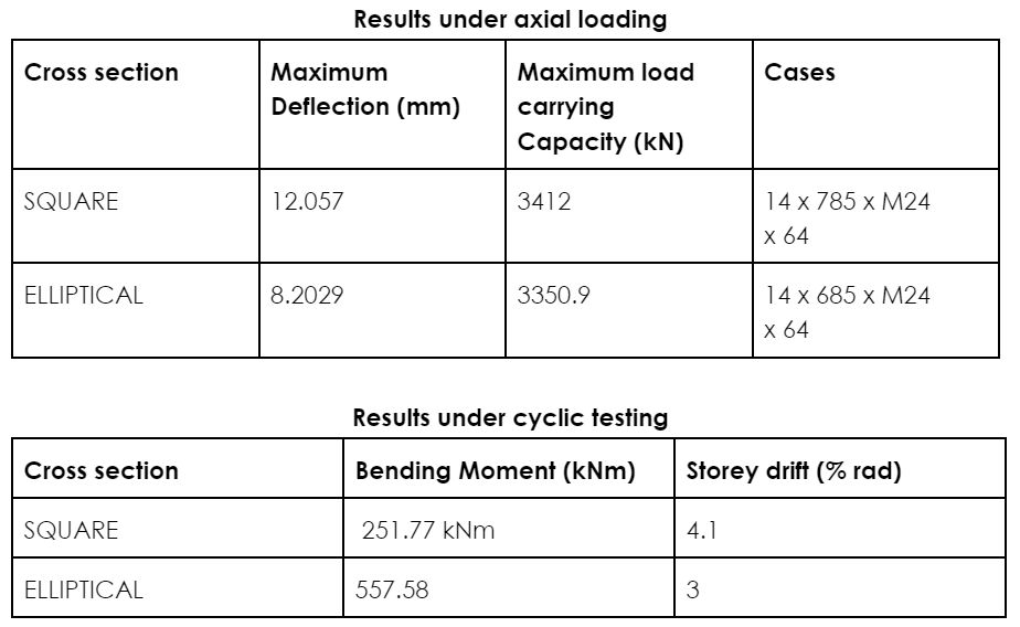
Research has not been done so far by changing the splice and bolt parameters on square and elliptical cross sections of steel tubular columns with deconstructable splice joints. The square cross-section shows a maximum load-carrying capacity of 3412 kN under axial loading compared to the elliptical section. The structure can withstand up to 12.057 mm deflection compared to the elliptical section which can withstand only 8.2029 mm. Hence more ductility is shown by the square section. The steel tubular columns with deconstructable splice connection with maximum load give greater strength.
Square sections have a larger moment of inertia than tubular sections. This means that a square section can offer better bending and torsion resistance for a given cross-sectional area, making it structurally efficient. When compared to tubular sections, square sections frequently have simpler connection details. The simplicity of linking and connecting square pieces to other structural parts is made possible by their straight edges, which also help to simplify design and construction. For square column cyclic loading test almost gave the same results obtained from the experiment with 0.8% error and storey drift of 2.44. A maximum bending moment of 251.77 kNm and a storey drift of 4.1 was obtained from ANSYS software. 3D finite element models were developed and tested for cyclic loading for the elliptical cross-section which showed a maximum moment of 557.58 kNm with 3% drift.
As per FEMA protocol, the structure is seismically stable if it takes about 2-4% of drift. Hence square and elliptical cross sections can withstand seismic action. From the parametric study conducted on a square cross-section we can conclude that since it is a symmetric section, a higher strength case is always shown by the structure with maximum thickness, length, diameter and number of bolts. Overall structural performance is shown by column. When these parameters are reduced load carrying capacity is also reduced. For the elliptical cross-section (being an unsymmetrical section) maximum strength case is shown with higher thickness, diameter and number of bolts. A splice length of 685 shows more load-carrying capacity than 785 mm. Under cyclic stresses, steel columns may suffer progressive deformation including local buckling and stiffness loss.
Contributed by:
Nehana VG, and Krishnachandran VN, Department of Civil Engineering, NSS College of Engineering


