
The use of ‘cables’ in structural application dates back to primitive times when ropes of vines and creepers served to cross small gaps in suspension forms. Such ropes were then combined with non-metallic decks and supporting towers (timber or stone) to construct early suspension bridges, and, steel was employed about two hundred years ago. The development of modern cable structures in earnest started in the late nineteenth century with suspension bridges followed by other forms. This became possible with the availability of high-strength steel. Technological developments in recent decades have raised the possibilities of utilizing cable structures many notches. A simply suspended cable is a very efficient ‘tension’ structure and can combine effectively with other structural elements of structural steel, concrete, composites, etc. for long slender structures or wide spans. The various possible applications are in Guyed Masts, used to carry flags, lights, and communication equipment, Ropeways used over single or multiple spans, support a Cooling Tower ‘skin,’ – an uncommon but a good solution which has been used, Roofs, of which there is a wide variety, and, cable bridges.
Cable-stayed and suspension bridges (or hybrids) are essentially combinations of cable ties, Catenaries, towers, and girders [1, 2, 3]. There are various configurations for cable-stayed bridges, and, geometrical proportions chosen for the same can affect the economy of the system considerably. The common range for the main span length of these bridges is 150 – 500m, though there do exist examples that are outside this range too. The range of span length between 500 – 2000m plus is generally occupied by suspension bridges.
Cable-stayed roofs employ a stiff deck supported by cable stays. Simply suspended cable assemblies produce a synclastic surface to support the roof cladding but have to be weighed down to avoid getting blown up by wind suction. Counter-stressed trusses and networks overcome this handicap of a ‘simply’ suspended system and lightweight roof claddings can be supported over these in the form of a cylindrical surface, a dome, a saucer, a hyperbolic paraboloid, and so on. Air-supported Membranes reinforced by cables or other light elements are another versatile roofing solution. It is worth noting that whereas cable roof systems are light, the support structures can often be required to be formidable. The ingenuity of the designer is involved as much in conceiving the appropriate support system, as in choosing the cable arrangement. Parameters such as geometric proportions, loading, type of cladding, and required stiffness have to be reckoned apart from architectural considerations, to produce the most efficient design [4, 5, 6]. Spans of the order of 150m have been achieved using cable roofing systems.
In India, the use of cable structures has been rather limited. Though, as shown later in this paper, there is much-increased usage of cable-stayed road bridges (including the extra-dosed type) in the last 3 – 4 decades. In this respect, the country is beginning to match international standards in technology. The application of suspension bridges is only in lighter and smaller ones, often only for pedestrians. The use of cable-supported roofs has almost invariably been in the form of fabric types in the last two decades.
The following sections trace briefly, the growth of cable structures and the factors responsible for it, besides other special features, which are special to this type of structure. A separate section on Cables is included too, though it is brief.
Patterns of Growth & Responsible Factors
Cable systems have been used in different kinds of applications, as mentioned already. However, the major user of steel cables has been in bridges, stayed or suspension, and to a lesser extent, roofs. Though these structural forms have been around for many centuries, it is pertinent to trace their growth in a more modern sense within recent centuries.
Suspension Bridges
The first suspension bridge using cast iron chains was built in Tibet in 1620, and, the earliest versions of cable bridges of modern times, which used steel ropes, appeared about 250 years ago. If one looks back at the nineteenth-century developments, when increasing spans were being attempted, the key concern was safety under own weight and applied to load. Provision of adequate stiffness was an important aspect, which was addressed variously, by stiffening girders or adding stays, not quite realizing the influence of ‘gravity’ stiffness.
It would not appear that the importance of torsional stiffness was quite realized. In the earlier half of the Century, there was no theoretical backup worth counting on. So, it was engineering skill and intuition that played a big part. Thus, the work of Roebling stands out through his design of several suspension bridges, capped by the Brooklyn Bridge.
He was fully conscious of the need to introduce adequate stiffness. This he achieved in the Niagara Falls Suspension Bridge and later the Brooklyn Bridge, by introducing deep trusses and adding stays to the suspension system. The Niagara Bridge with a 280 m span, built in 1855, had a double-deck system and carried a railway at the top. It had such high stiffness that under a full train load the maximum deflection was less than 25 cm at the center.
His design of the 486m main span Brooklyn bridge, constructed in 1883 with a greatly reduced stiffening girder depth, is indicative of the realization of the rather high stiffness of the Niagara Bridge, and, implicitly the acceptance of the fact that the presence of the cable also contributes to the overall stiffness of the bridge. It does not appear that the importance of wind effects on such bridges was properly understood, despite failures such as the Brighton Pier (1834), the Wheeling Bridge (1854), and, Niagara – Clifton (1889) in wind storms, Much larger spans then followed the development of the ‘Deflection Theory’ for suspension bridges.
George Washington Bridge, San Francisco – Oakland Bay Bridge, Golden Gate Bridge, and the like, and the utility of the concept used in the deflection theory showed its enormous merit. These bridges were followed by the Tacoma Narrows Bridge, which unfortunately failed soon after its completion. It may be of interest to note that the Washington bridge with a span of 1066m, had no stiffening girder, to begin with, but had a width-to-span ratio of 1/33. Golden Gate Bridge with a 1280m span had a width-to-span ratio of 1/47.
The Tacoma Narrows bridge with a span of 853m, had a width/span ratio of 1/72 and a plate girder with a depth as low as 1/350 of the span. The Tacoma Narrows weighed 4.25 t/m, while the Golden Gate was 21t/m. The Tacoma Narrows bridge designers virtually tested the ‘deflection’ theories to the limit in providing a very light and shallow stiffening girder.
Though this, despite its shallowness, was adequate for the vertical loads, the deck system proved to be inadequate to withstand aerodynamic oscillations that occurred only 4 months after it was opened, only under mild winds, and collapsed. The failure created a storm of sorts amongst bridge engineers and civil engineers alike to usher them to research the field of bridge aerodynamics. Broadly speaking, it was understood that the failure of the bridge was due to the large deformations caused by the aerodynamic mechanism called ‘flutter’, and, that the bluff shape of the shallow plate girder, combined with a small width, and, the resulting low torsional stiffness lead to this unfortunate destruction of a major bridge.
A much better understanding of cable bridge aerodynamics, followed by intensive research, lead to the adoption of the suspension bridge system with greater confidence, and the Akashi Kaikyo bridge with a main span of 1991.6m (which stood as a record for the longest span for more than 20 years), and, now the 2023m Canakkale bridge in Turkey (Fig. 1), stand as testimony.
In India, the system has been deployed in a very limited way for small spans and light loads only, as mentioned already, though there are hundreds of such bridges.
Cable Stayed Bridges
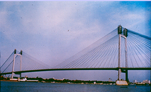
The development of cable-stayed bridges can be said to have begun with the construction of a bridge in Germany by Loscher in 1784. By the time of World War II, the era of modern cable-stayed bridge design was just about to commence. The first modern cable-stayed bridge was the Stromsund Bridge designed by F. Dischinger built in the 1950s in Sweden with a main span of 183m and two symmetrical back spans of 75m each. More than 1000 cable-stayed bridges have now been built worldwide. A significant number of cable-stayed railway bridges have also been constructed. More recently very elegant pedestrian cable-stayed structures have been built and have become landmark structures. Today, cable-stayed bridges have firmly established their unrivaled position as an efficient and cost-effective structural form in the 200m to 1100m span range and even more (see Fig. 2 which shows the 1104m span Russky bridge in Russia). The cost-effectiveness and the general satisfaction with their aesthetic aspects have propelled this span range in either direction, with both increasingly shorter and increasingly longer spans being designed and constructed at present. Usual spans of CSBs are larger than those of extradosed bridges and shorter than suspension bridges for the reasons of structural design & economy, with overlaps on either side. Cable-stayed bridges (CSB) have become increasingly popular in India over the last 40 years. The journey started with a small 73m span footbridge across the Ganga canal at Roorkee (1982), the first Indian road bridge across the new Ganga channel at Hardwar, 130m long (1988), and now has such fine examples as the Vidyasagar Setu, Kolkata (Fig. 3), the Worli-Bandra Sealink bridge, the Signature bridge at Wazirabad, and so on. The more recent development has seen the deployment of extradosed bridges, which can be described as a variation of the cable-stayed system, with a somewhat different philosophy of design. India has adopted this design approach in a big way. A recent example is the Ara-Chapra bridge over the Ganga, the longest extradosed bridge in the world.
Cable Roofs
A historical review of cable (or tension, suspended) roofs suggests that the earliest version of a tensioned roof was a tent. The use of tents was traditional in cold climates such as in Siberia or hot desert regions and has a history of thousands of years.
The principle of using tensioned cables in the construction of roofs was first illustrated, according to recorded history, in A.D. 70, when the 189 x 156 m Roman Coliseum was achieved. A few suspended roofs were built in Russia at the end of the 20th century and ranged in span to about 60 m. In these roofs, a crisscross lattice of steel strips was used in place of cables, to support the roof surface.

Although the system was since used off and on, there was no appreciable advance in the construction of cable roofs until the 1950s; thus, this still is a comparatively young system of roof construction. The real developments in the analysis, design, and construction of cable roofs occurred only after the Raleigh arena, designed by Nowicki, was built in the United States in 1953, and substantial progress has taken place since.
The main load-bearing element in suspended roofs is a steel cable, which is occasionally combined with struts or light flexural members. Usually, such roofs are also light in weight and would therefore be limited to low gravity stiffness, unless the system is preloaded. Cable-suspended roofs can be classed as all-tension structural systems. There are numerous exciting examples worldwide.
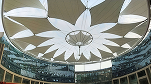
In India, the system has been used during the last 2-3 decades, as mentioned already, but more or less exclusively with fabric roofing. The prime movers for this development have been Messers Construction Catalysers, Pune. Some of the examples are ONGC Corporate Office, New Delhi (Fig. 4), Amusement Park Station at Rohini, New Delhi, Rapid Metro Stations, Gurgaon, Deccan Harvest, Pune, Archery Training Venue, Sports Complex, New Delhi, Vasant Square Mall, New Delhi, the roof of the Bhopal Airport.
Factors Responsible
A basic factor that needs to be recognized, is that a steel cable in its suspended form is a highly efficient structural form. Ties and struts carry axial forces in direct tension or compression respectively, and, are thus well understood to utilize constituent materials efficiently. As far as transverse loads are concerned, members in bending do not offer the same benefit, but a suspended cable does. Nevertheless, being slender, Cables can only carry tension. Thus the development of very high tensile strength steels (>1800 N/mm2), with a high strength-weight ratio, from which wires for cables are made, makes cables very suitable for longer span applications (see in a subsequent section for more information on cables). Besides the improvements in steel strengths, there have been improvements in other constituent materials such as concrete too. It has thus become possible to obtain lighter cable-supported structures, an important objective when designing longer spans.
Besides the above-mentioned basic factor, the growth of cable structures over the last 100 years has been ushered in due to many developments. These include materials as already mentioned, more effective tools for analysis and design, construction techniques and technology, greater understanding of wind effects particularly for bridges, backed up strongly by the exponential growth of electronics leading to hugely improved computing capabilities, as well as instrumentation for experimentation on both models as well as prototypes of structures.
Whereas the developments of the ‘deflection theory’ brought in a great change in the design of suspension bridges, the scenario today in respect of capabilities for analytical work is far different from the one in the 1950s. Thus, in the 1950s, designers preferred cable-stayed bridges with only a few cables, with large spacing longitudinally. This also meant that only small to medium spans were adopted. The advent of the high-speed digital computing systems in the 1960s, and, their continued upgradation, backed up by the most sophisticated software packages based on the FEM and matrix methods, which can tackle both linear as well as non-linear static and dynamic analysis of structures of great complexity and size, altered this limiting scenario.
The growth of electronics led to the availability of much-improved sensors and monitors and aided better-quality experimental work. Automation and higher capability of construction equipment raised the capability to construct larger structures. As just one example of capabilities in fabrication and construction, it is worth mentioning that for the Akashi Kaikyo Suspension bridge, 80m diameter steel caissons were fabricated offshore and towed by boats over water (Fig. 5) to the location of the tower.
(to be continued….)
Contributed by Prof. Prem Krishna, Professor & Head (Retd.), Department of Civil Engineering, IIT Roorkee