

Grid shells are structures with the shape and rigidity of a double curvature shell, consisting of a grid instead of a continuous surface. Pioneered in 1896, by Russian engineer Vladimir Shukhov, grid shells were first used in the Nizhny Novgorod exhibition pavilions, with Shukhov also developing the mathematics for their analysis. In 1975, Frei Otto designed the Multihalle grid shell in Mannheim, Germany, using a hanging chain model for form-finding and the SAP4 computer program for strength calculations. Modern computers and software have since simplified form finding, topology optimisation, and strength calculations for grid shells.
Generation of Free-form Surfaces
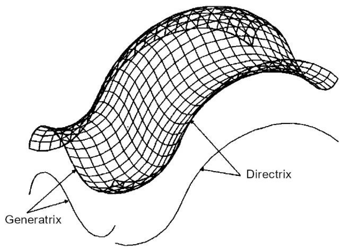
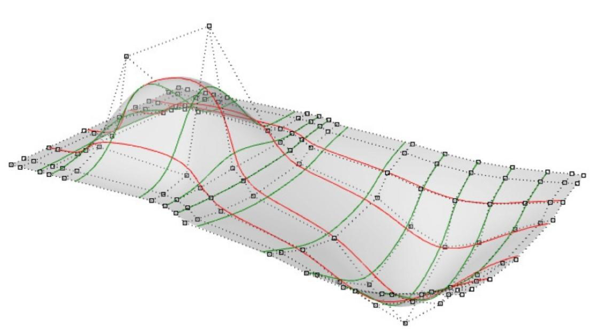
Free-form surfaces are classified into Translation Surfaces and NURBS. A Translation Surface is created by moving a curve, called the generatrix, parallel to itself along another curve, the directrix, resulting in a net with planar meshes or panels. NURBS, or Non-Uniform Rational B-Splines, describe free-form curves and surfaces mathematically. A NURBS surface is defined by a grid of curves running in the u- and v-directions, which are the intrinsic coordinates of the surface in two-dimensional space.
Meshing
Having defined a free-form surface, the next step is to convert the surface into a mesh. The most common mesh types are triangular and quadrilateral – warped or planar Valence of a node which refers to the number of structural elements connected at the node. A surface defined by a triangular mesh has higher valence as compared to a quadrilateral mesh. The higher the valence, the higher the number of variables required to be accommodated at nodes.
Free-form grid shells come with their unique set of challenges which must not be ignored.
Beam-Panel Connection
Beam-panel connections can be significantly simplified if the beam’s top surface is parallel to the tangent plane of the envelope surface, otherwise, a high kink angle appears between panels and beams. This property also affects the mechanical efficiency of beams against wind load and light transmission.
Geometrical Torsion at Nodes
The normal vector to an arbitrary curve on a curved surface rotates around its tangent vector. On a grid shell, a straight segment thus undergoes rotation about its longitudinal axis.
Buckling
As compared to continuum shells, grid shells have limited load paths which are prone to multiple forms of buckling as follows:
Member buckling: Due to the low slenderness ratio of the member
Snap through of one or several nodes: Caused by low moment capacity of the node
Global instability: In high compression areas
Combinations of the above modes
Optimisation for Manufacturing
A doubly-curved free-form grid shell typically comprises nodes of different shapes with multiple variables, incurring high manufacturing costs. A clustering–optimisation strategy is used to reduce the number of different node types. In clustering, nodes are divided into different groups, with similar shapes. In optimisation, nodes within the same group are transformed towards congruence while closely approximating the target surface. This transformation makes it imperative that nodes have built-in angular tolerance.
All of the above-stated challenges relate to the proper design of nodes. Many node connection systems have been developed to address these requirements with varying degrees of success.
SBP-1
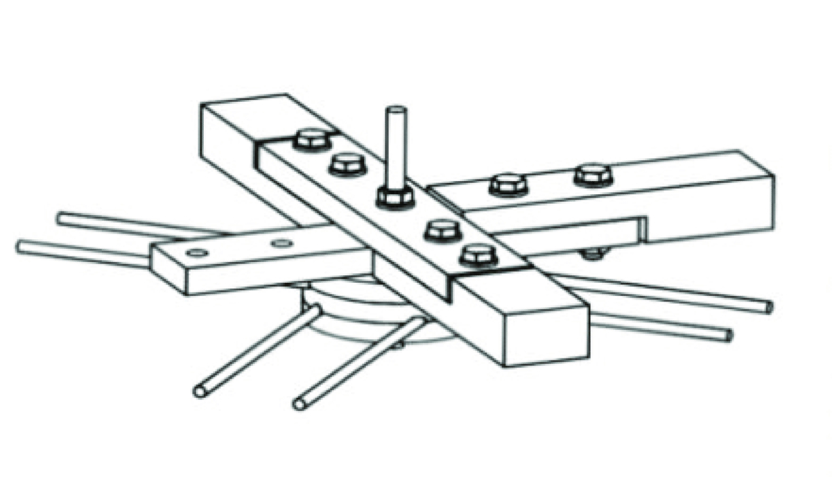
The splice node connection SBP-1 which was developed by Schlaich Bergermann & Partner, Stuttgart, Germany in 1988. The end of the beam is fabricated as half of a fork-shaped flat plate to be connected with a splice by two or more bolts so that it has a single hear plane in the connection. Through the central bolt, the horizontal angles between beam members can be adjusted. As for the vertical angles, the splice plate has to be folded. Twist angles can be controlled only in a limited range. The low section height may cause a low transfer of bending moment.
SBP-2
The splice node connector SBP-2 is modified from the previous version of SBP-1. Here two splice plates can be attached on both the top and underside of the beam. They are all connected by two or more bolts in double shear. The limitations for horizontal, vertical and twist angles are almost the same as the previous version of SBP-1. Due to double shear in the joint, this node connector system can bear higher bending moments than the one of SBP-1
POLO-1
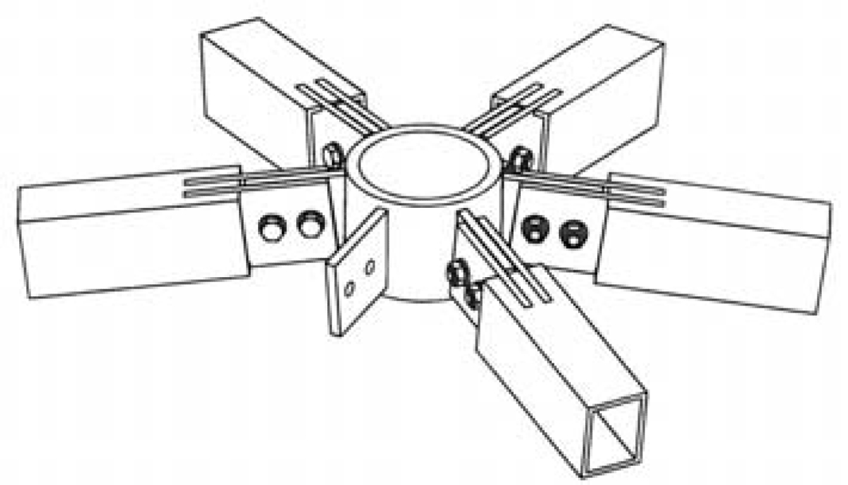
Another splice node connector POLO-1 was developed by Polonyi & Fink, Cologne, Germany. This connector consists of a cylindrical or prismatic core and up to six vertical splice plates. The end of the beam was fabricated as a fork-shaped form to be welded to two steel plates, and then the splice of the node was inserted into the end of the beam and connected by two or more bolts. Horizontal, vertical and twist angles of the structural members can be adjusted by changing the geometry of the splice plates. This system can transfer a high bending moment.
SBP-4
The SBP-4 end-face connector by Schlaich Bergermann & Partner consists of two cross-shaped plates and four end plates welded together. Structural members connect to the node end-faces with butt welds and can be temporarily fixed with bolts during erection. A clamp for cable bracings is attached to the top plate by four bolts. Horizontal angles are accommodated by the cross-shaped plates’ geometry, while vertical angles are adjusted by the machined node end-faces. Twist angles are limited by imperfections. The considerable section height allows the transfer of high bending moments, up to the full member strength.

WABI-1
The WABI-1 node, developed by Waagner-Biro AG, Vienna, is a welded end-face connector featuring a star-shaped plate with 5 or 6 arms, each extending between adjacent structural members. Made from thick plates cut perpendicularly, the node has a double mitre cut on structural member end-faces to match the node gap between arms. The node plate’s thickness is less than the height of the connected members. The top and bottom node surfaces are connected by fillet welds, and the sides by butt welds. Horizontal, vertical, and twist angles are accommodated by the double mitre cuts, allowing high bending moments to be transferred.
OCTA-1
Another end-face connector OCTA-1, was developed by Octatube Space Structures BV, Delft, Holland, as a modification of the Tuball node system. The node is made from a hollow sphere with openings at the top and the bottom. Each structural member is connected to the node sphere by two bolts, which are mounted from the inside of the hollow sphere. Horizontal, vertical and twist angles of structural members at this node can be accommodated by the geometry of the two bolt holes for each member. Direct support of cladding elements by the members across the node connector is not feasible.
MERO-1
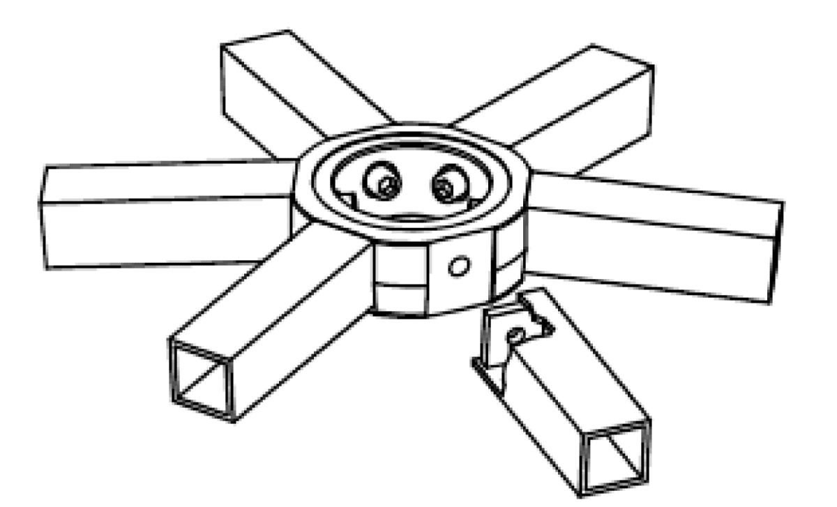
In 1994, MERO GmbH, Wuerzburg, Germany published a series of end-face connectors along with the bowl node, which was called ‘MERO Plus’ [MER94]. One of these node connectors is the cylinder node MERO-1. The node is made from a hollow cylinder with openings at the top and the bottom. Each structural member is connected to the node cylinder by two bolts, which are mounted from the inside of the hollow cylinder. Horizontal, vertical and twist angles of structural members can be accommodated by the geometry of the machined plane surfaces at the node. The connection enables the transfer of relatively high bending moments.
MERO-2
One more ‘MERO Plus’ connector is the block node MERO-2. The node is cut from a thick plate. Each structural member is connected to the block node by one or two bolts, which are mounted from the inside of the structural member. Hence, the member must be a hollow section profile like RHS, SHS or CHS. Alternatively, the members can be welded to the node. Horizontal, vertical and twist angles of structural members can be accommodated by the geometry of the machined plane surfaces at the node. The bending capacity is similar to the capacity of the cylinder node MERO-1.
MERO-3
Another ‘MERO Plus’ connector is the dish node MERO-3. This node consists of a dish, i.e. a hollow cylinder with a bottom plate. The structural members are connected to the node by only one bolt. Horizontal, vertical and twist angles of structural members can be accommodated by the geometry of the machined plane surfaces at the node. The bending capacity of the connection is rather small.
Innovation
As will be noticed, each node type can solve problems associated with free-form grid shells to varying extents. A connector node is now developed as described below, which addresses the challenges innovatively.
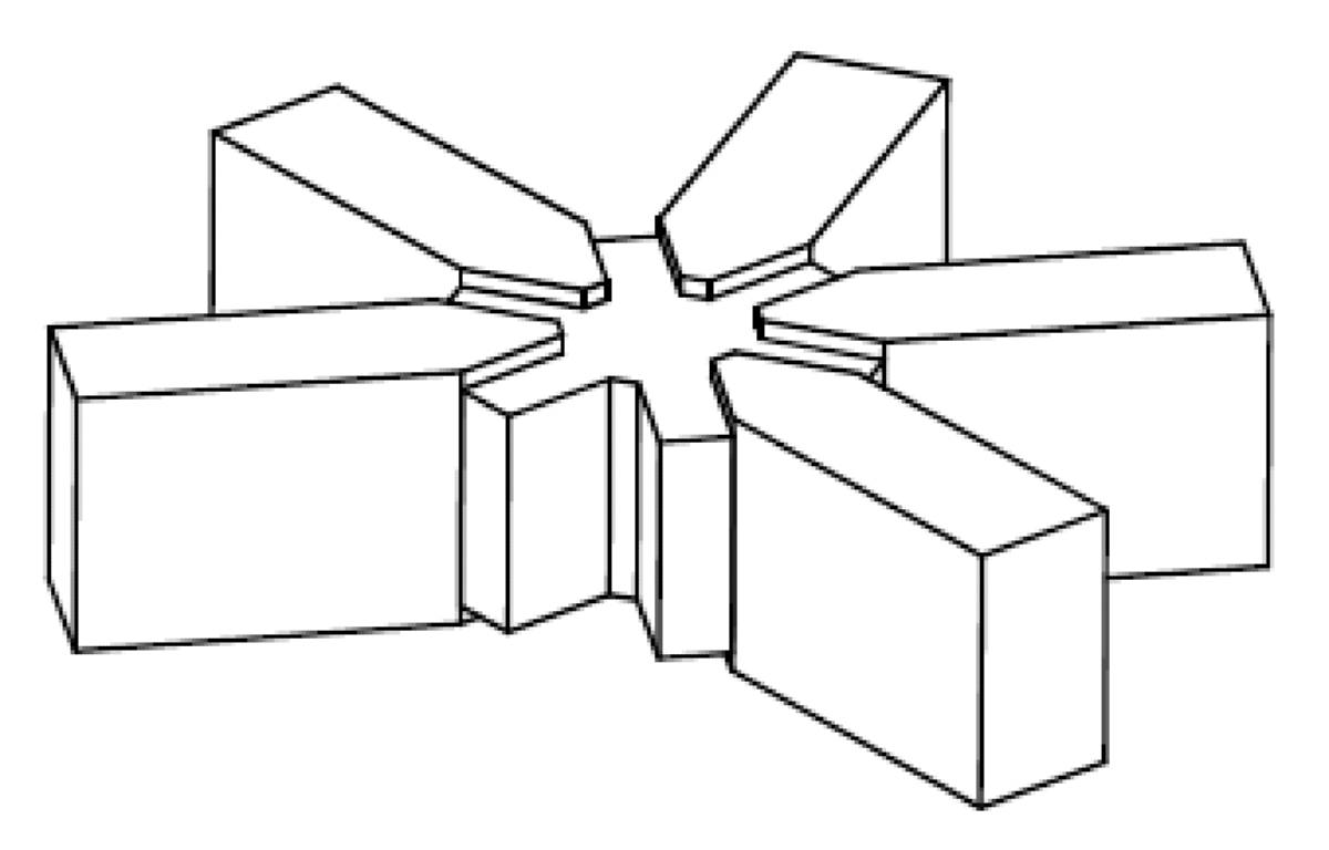
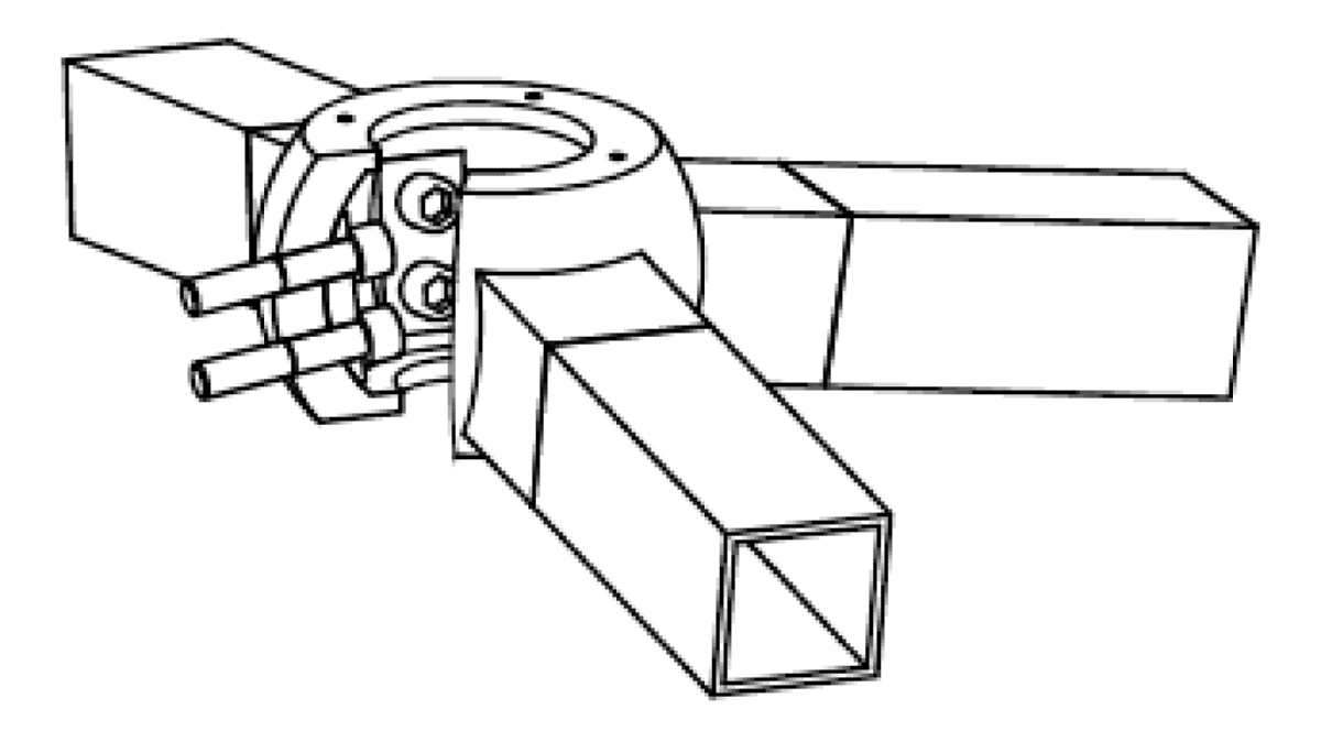
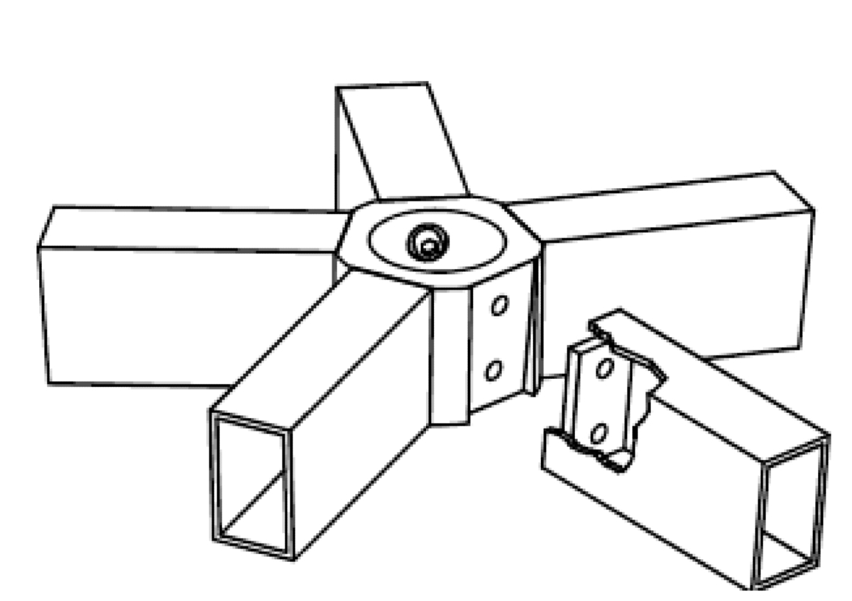
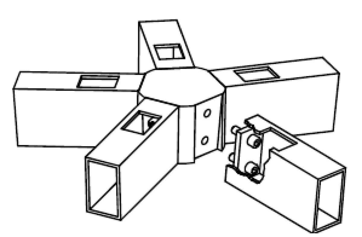
The connector node is made up of petals with at least two segments, in the form of triangles with apex angle θ and dihedral angle between adjacent segments α. Angles θ and α are selected such that the petal snugly fits on abutting struts. The petals are arranged side-by-side forming node-top and node-bottom parts of the connector node. Struts are fixed to each segment of the petals of the node tops and node bottoms by a mechanical fastening.
The adjacent petals of the node-top and node-bottom parts are oriented such that the fold lines of the petals of the node-top and edges of the petals of the node-bottom are parallel and lie in the bisector plane of the dihedral angle α and contrariwise fold lines of the petals of node-bottom and edges of the petals of node-top are parallel and lie in the bisector plane.
Adjacent petals may be welded together for additional stiffness and the node-top and node-bottom parts of the node may be conjoined by spacer elements.
This cost-effective node can transfer axial, shear and bending moments, has torsional flexibility and kink at the beam-panel interface is avoided.
– Contributed by
Rudra Nevatia, Consulting Engineer


