

Steel is a popular construction material due to its strength, flexibility, cost-effectiveness, durability, recyclability, and eco-friendliness. Its rapid global development stems from its advantages, such as speedy construction, handling wider spans and heavy loads, and greater earthquake resistance than concrete.
Conventional steel buildings (CSB) are built on-site with hot-rolled members and trusses, requiring significant design input and time. These structures often use unsuitable hot-rolled steel sections, leading to increased weight and heavier foundations. Pre-engineered Buildings (PEB) address these issues by optimizing steel usage through frame geometry aligned with internal stress diagrams, reducing overall weight. PEB components have variable cross-sections based on stress requirements and are designed in the factory for on-site assembly.
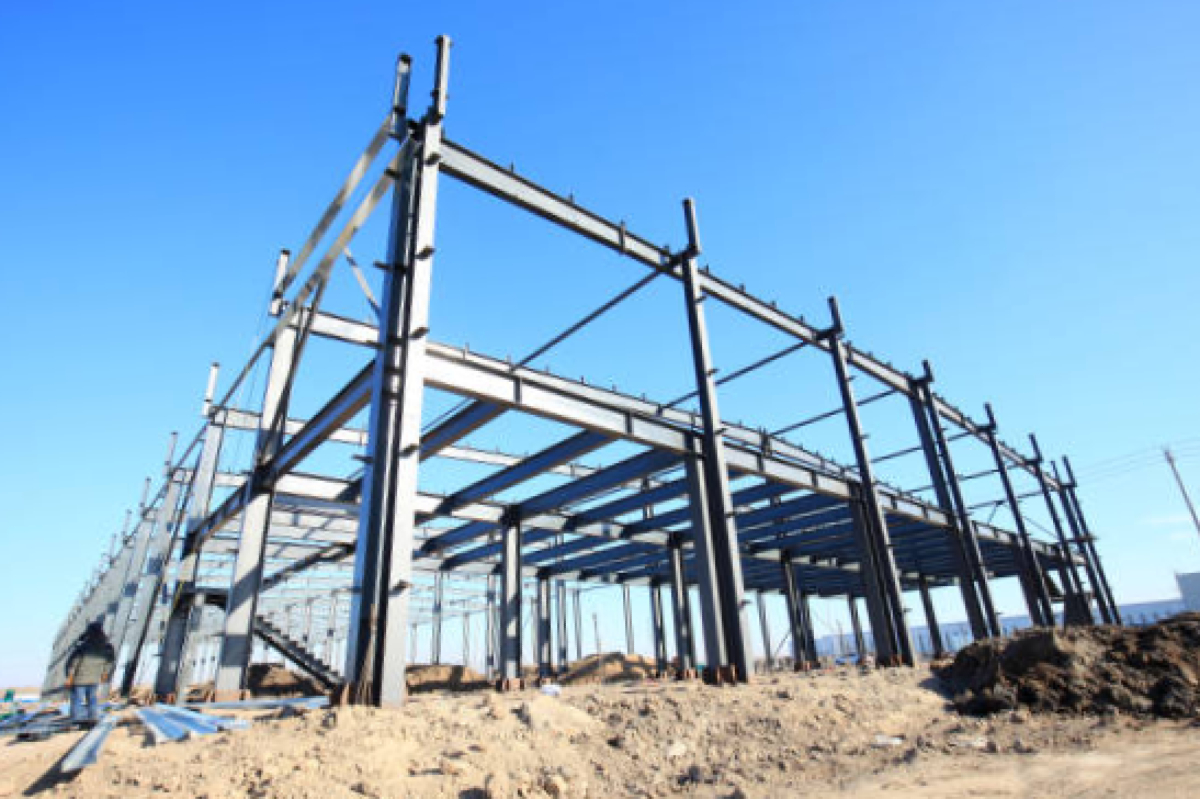
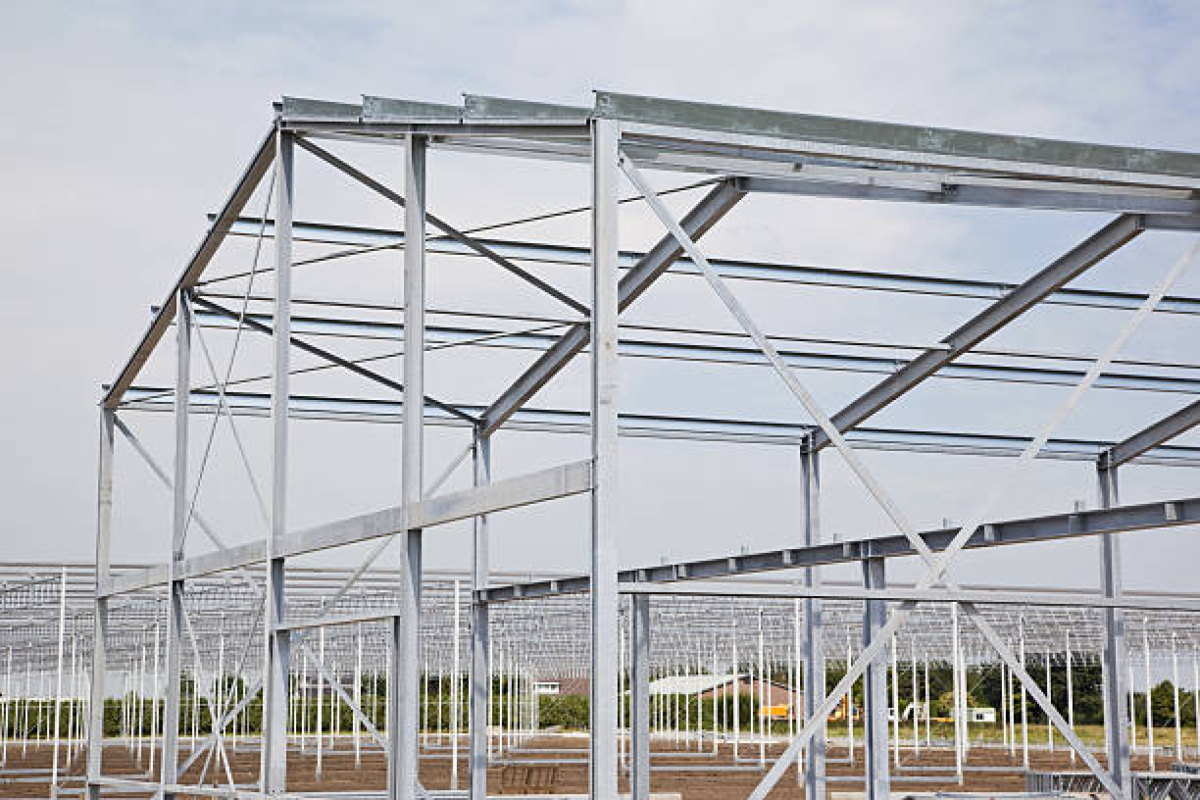
A PEB is a cohesive steel structure featuring rigid frames, cold-formed secondary structural members, and bracing, with metal sheets on the roof and exterior walls. Recently, PEBs have become more popular due to their energy and cost efficiency, lightweight nature, and quicker erection time compared to CSBs. PEBs are versatile, and used in industrial facilities, warehouses, restaurants, and medical offices, making them a preferred solution for various projects.
Components of PEB
The PEB consists of different components viz. primary members, secondary members, and some miscellaneous members. The primary members are manufactured out of hot-rolled steel sections and consist of columns and rafters which are generally provided with tapered shapes. The purlins and girts are the secondary members which are generally cold-formed members. The members include sheeting, gutters, trims, and other accessories categorised under miscellaneous members.
Analysis and design of PEB
Analysis and design of PEB provided with different types of bracings (viz. diagonal, X, V, and K) is carried out using STAAD Pro software.
The analysis and design of the PEB structure are carried out using STAAD Pro software by following the steps given below.
1. Preparation of 2D portal frame of PEB and assigning supports
2. Defining sectional properties
3. Defining the loads
4. Assigning the loads on a 2D portal frame
5. Transformation of 2D portal frame to 3D geometry
The step-wise procedure adopted for the analysis and design of PEB using STAAD Pro software considering the geometrical and other details is presented below.
Step 1: Preparation of 2D portal frame
As per the guidelines of IS: 800–2007 for roof slope and using the geometrical sizes considered for PEB, a 2D frame with fixed supports to its columns is created using STAAD
software.
Step 2: Defining sectional properties
The members of the 2D PEB frame thus generated are assigned different sections.
Step 3: Defining the loads
The analysis and design of PEB are performed considering dead load (DL), live load (LL), collateral load (CL), wind load (WL), and seismic loads (SL). The details of these loads are given below.
a) Dead load (DL)
The dead load consists of a uniformly distributed load (UDL) transferred to primary members from secondary members. The DL transmitted to the rafters of PEB is determined as given below.
– Calculations of DL on rafters:
The total DL transferred to the rafter from secondary members is calculated below:
– Weight of purlin: 5 kg/m2
– Weight of GI sheet (roofing): 5 kg/m2
– Weight due to solar panels, ducts, etc.: 27 kg/m2
(Collateral load)
– Weight of eave strut: 10.7 kg/m2
– Total load: 47.7 kg/m2
Thus, the total load on the rafter per m length is determined as:
Load on rafter = Total load x bay spacing
= 47.7 kg/m2 x 7 m (bay spacing) = 333.9 kg/m (3.33kN/m)
b) Live load (LL)
The LL consisting of loads due to the movement of workers (e.g., repair works), equipment, and materials are considered. The total LL of 75 kg/m2 (0.75kN/m2) has been considered for the analysis and design as per the guidelines of IS: 800–2007.
c) Wind loads (WL)
The WL calculations are performed as per the guidelines to the IS:875–2015 (Part 3), for all the terrain categories and considering the internal coefficient pressure (Cpi) as ± 0.5 for a partially enclosed structure. The wind load acting on the PEB members is presented below.
i) WL acting on principal rafters
The external pressure coefficients (Cpe) for 1/10 roof slope and wind angles of 00 and 900 are used for determining the WL acting on the rafters of the PEB structure as per clause 7.3.3.2 of IS: 875–2015 (part 3).
d) Seismic load (SL)
The PEB has been analysed and designed considering all the seismic zones viz. II, III, IV, and V and medium type of soil. The design seismic load (Vb) is determined as per the formula given in IS:1893.
Vb = AhW———————————Eq. (1)
Where,
‘Ah’ is the design horizontal seismic coefficient and
‘W’ is the seismic weight of the structure.
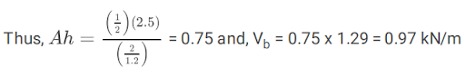
The design horizontal coefficient (Ah) is determined by using the following formula
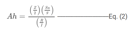
Where,
Z = 1, seismic zone factor as per Table 3 of IS: 1893
Sa/g = 2.5, design acceleration coefficient for the medium type of soil
R = Response reduction factor
I = 1.2, importance factor of the structure
e) Total load on the rafter of the 2D PEB Frame:
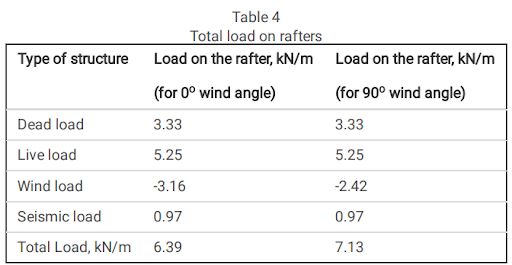 f) Total load on the columns of the 2D PEB Frame:
The total load transferred from the PEB rafters to their respective columns as obtained by STAAD Pro software is 42.56 kN.
Step 4: Assigning loads on 2D PEB frame
The loads as determined in the previous step are assigned to the rafters of the 2D PEB frame and the analysis is performed using STAAD Pro. The results of the analysis for the responses viz. displacement and natural time period are presented in the below Table.
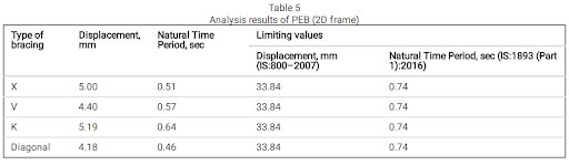 From the above Table, it is observed that the responses viz. displacement and natural time period of the 2D PEB frame are found to be within the limits specified by IS:800–2007 and IS:1893 (Part 1):2016. Therefore, it is confirmed that the sections adopted for all the members of the 2D frame are adequate in size and hence, it is stated that the design of PEB is safe.
Step 5: Transformation of 2D PEB frame to 3D PEB structure
The 2D PEB frame is transformed into a 3D PEB structure and then all the required components viz. purlins, wall girts, and bracings are introduced to perform the analysis and design of the PEB structure under consideration.
After the transformation of the 2D PEB frame to a 3D PEB structure, the STAAD Pro software performs the analysis and the results are provided in a tabular form. The results of STAAD Pro analysis were thus obtained for the responses viz. displacement and natural time period and also the overall weight of PEB structure is discussed in the next section.
Results and discussion
The results of the analysis of PEB structure provided with different types of bracings (viz. X, V, K, and diagonal) are obtained by using STAAD Pro software for the responses (Re.) viz. displacement (D) and natural time period (T).
It is observed that the displacement and natural time period values are found to be minimum for the PEB provided with diagonal bracing for all the seismic zones. Further, it is observed that the lowest values of displacement and natural time period of the PEB with diagonal bracings are found to be for the seismic zone II. The variations in the displacement and natural time period values of PEB with different bracings for all seismic zones are shown.
Further, it is observed that the deflection of PEB with diagonal bracing reduces by 12.95% when compared with the average displacement values of PEB with other types of bracing (i.e., X, V, and K). Similarly, the natural time period of PEB with diagonal bracing reduces by 19.35% when compared with the average natural time period values of PEB with other types of bracing (i.e., X, V, and K).
And the variations are shown in the displacement and natural time period values of PEB with diagonal bracings for seismic zones II respectively.
The deflection of PEB with diagonal bracing is reduced by 13.58% compared to the average displacement values of PEB with X, V, and K bracing types. Similarly, the natural time period of PEB with diagonal bracing reduces by 29.82% when compared with the average natural time period values of PEB with other types of bracing (i.e., X, V, and K) is shown.
Moreover, it is observed that the overall weight (Wt.) of the structure is found to be minimum for the PEB provided with diagonal bracings for all the seismic zones when compared to the PEBs provided with other types of bracings and for all seismic zones.
Lastly, it is observed that the overall weight of PEB with diagonal bracings reduces by 4.13% when compared with the average weight of PEBs with other types of bracings (i.e., X, V, and K).
Conclusions
The structural behaviour of PEB provided with different types of bracings (viz. X, V, K, and diagonal) subjected to wind and seismic loads is carried out considering seismic zones II, III, IV, and V for determining the efficient bracing system. From the study, the following conclusions are drawn:
1. The displacement and natural time period of the PEB provided with diagonal bracing are found to be less by an average value of 13% and 15.80% respectively when compared with corresponding average values of the displacement and natural time period of PEB provided with X, V, and K bracings.
2. A reduction in the weight of PEB provided with diagonal bracing is found to be more by 4.13% when compared with the weight of PEB provided with different types of bracing.
3. The results of the analysis of PEB provided with diagonal bracings go well in agreement with the results available in the literature.
Contributed by –
Pravin. P. Bharmal & Popat. D. Kumbhar, Rajarambapu Institute of Technology
Krishnakedar. S. Gumaste, Walchand College Of Engineering


 optimize steel and bracing for improved performance.)