HITEX Exhibition Centre is a renowned destination in Hyderabad, hosting a wide range of events, including corporate conferences, trade fairs, art exhibitions, indoor sports events, music concerts, and grand weddings. It has the capacity to accommodate audiences ranging from small groups to large crowds, with ample open space for parking. Before the construction of the current convention hall, the centre had three halls, each measuring 48 m x 72 m, with the ability to host 2,500 people per hall.
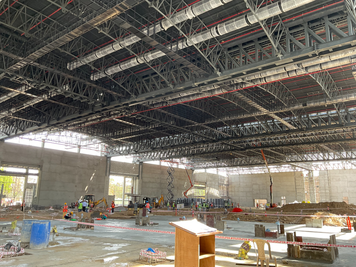
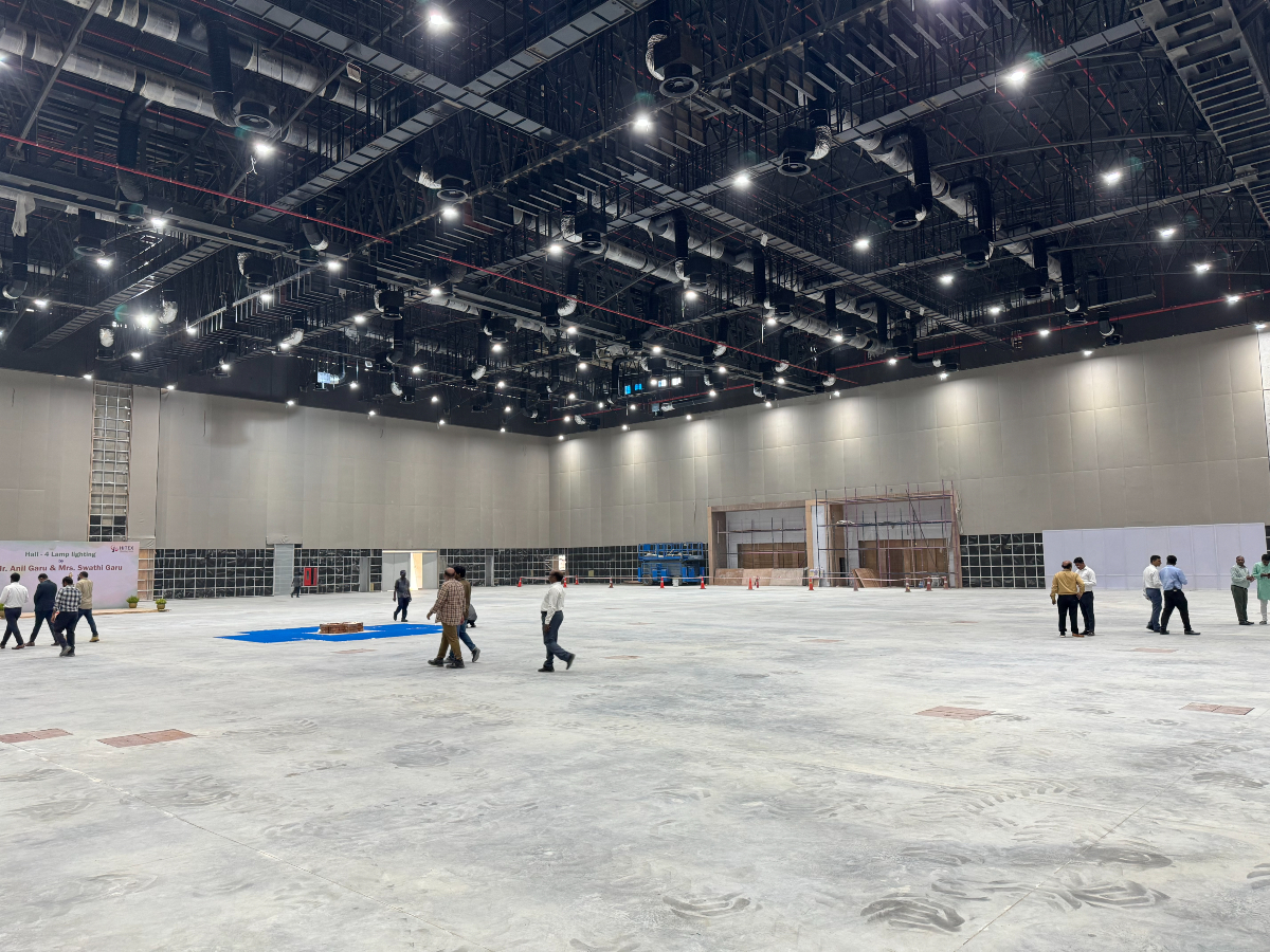
The present convention centre, Hall No. 4, at HITEX spans 86m x 120m, including a 12m x 120m pre-function area featuring a grand double-height foyer of 6m. The first and second floors are designated for smaller conferences, corporate boardroom meetings, and birthday functions. Beyond the grand foyer, a vast column-free hall measuring 68 m x 120 m with a ceiling height of 12.8 m is designed to accommodate up to 8,000 people. This hall can be divided into four, three or two separate halls, or remain as a single space, using partitions suspended from the roof. At the rear of this hall, a 6 m x 120 m MEP service area is planned, along with VIP rooms. The entire facility is fully air-conditioned.
Collaborative Vision
SEP Architects, represented by Architect Rupum and Architect Avhijit Dev, are the key architects for this prestigious project, with valuable input from Architect Dr. Cox from Australia. The design of this convention centre carefully addresses all the functional requirements typical of such a facility. The architectural plans ensure seamless interconnection between this hall and the other three existing halls. Circulation has been thoughtfully planned, providing separate entry points for different purposes, including general entry, VIP entry, and service entry. The front elevation is uniquely designed with circular columns and a wave-like façade.
For the design of this massive structure, three mini structural models were prepared and presented to the client and architects. Following extensive brainstorming sessions, a consensus was reached on the final structural design.
Mastering Spans
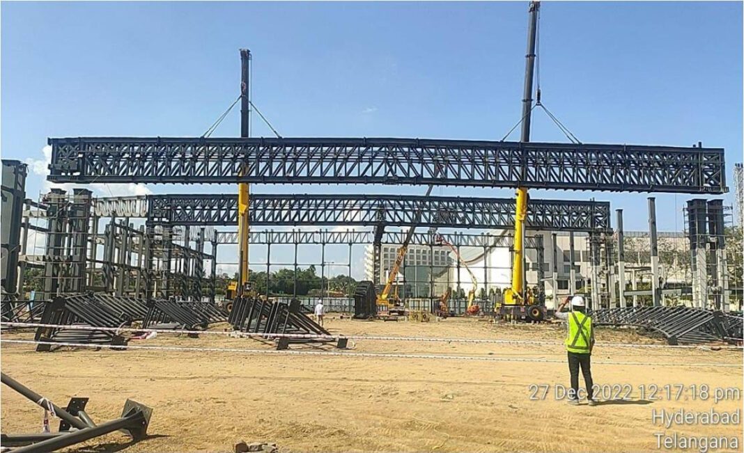
To design the 68 m column-free space, a steel lattice structure was selected. The bottom had to remain flat to accommodate the partition walls, and these lattices were spaced at 27 m intervals. A single lattice was insufficient for such a large span, so a double lattice with lateral connections was planned to reduce the height of the lattice and control deflection.
Supporting such a large lattice span required columns with significant moment capacity. Balancing the large end moments posed a challenge, so a configuration of four columns on either side was adopted. This design converted the large end moments into axial compression with bending for the inner columns and axial tension with bending for the outer columns. By mounting the lattice on top of the columns, this configuration simplified the structure and allowed for a more economical design.
Overcoming Obstacles
The challenges in this project were significant, starting with the creation of a column-free space measuring 68 m x 120 m. The design also required the ability to divide the hall into four, three or two separate halls using partition walls. These partitions, running both along the length and across the width of the hall, imposed a substantial load of 1.2 tonne per metre, which needed to be suspended from the roof.
Another challenge was the storage of all partition walls in two rooms located at the extreme ends of the hall, with a total load of 120 tonne also suspended from the roof. Additionally, the construction of a 120 m long catwalk presented its own set of complexities.
Anticipating challenges during the erection process, provisions were made to ensure that any potential issues could be addressed to prevent untoward incidents.
Strength in Design
The columns are designed as box columns, constructed with steel plates and filled with concrete for added strength.
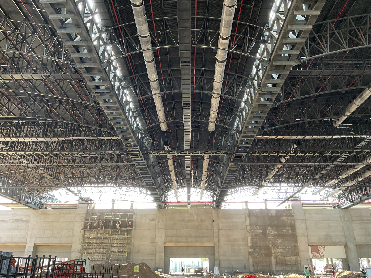
The main lattice is a double lattice, standing 3 m high, with lateral connections. The top and bottom chords are UB 457 x 191 x 74, while the vertical and inclined members are SHS 220 x 220 x 6 at the ends and SHS 180 x 180 x 6 in the middle region. The main lattices are spaced at 27 m intervals. To account for erection errors, self-weight deflection (140 mm), and deflection due to partitions (50 mm), an upward camber of 600 mm was provided. Each lattice weighs 120 tonne, and since it is top-mounted, slotted holes were added longitudinally to the bottom chords to allow for sliding due to the structure’s self-weight. Notably, the lattice slid 30 mm immediately after erection—a crucial consideration when dealing with large spans mounted at the top.
The cross lattice spans 27 m and is positioned every 5.6 m. This cross lattice is designed as a triangular lattice with a parabolic arch in the longitudinal direction. The lattice members include CHS 114 x 4.5 for the main chords and CHS 88.9 x 4.0 for the inclined sections. This triangular configuration was chosen to handle both longitudinal and lateral bending, as well as to ensure easier erection.
Purlins of size 122 x 61 x 3.6 are placed at intervals of 1380mm centre-to-centre.
Engineering Precision
After the foundations were completed with the requisite anchor bolts, all the columns were erected along with tie members. Since the columns were designed as box columns, concrete filling was proposed to increase stiffness and enhance fire resistance. The concrete-filled columns also facilitated the top-mounted lattice erection by improving load-bearing capacity, both vertically and laterally, ensuring stability even in the event of side impacts.
Prior to the main lattice erection, the exact sling points for the cranes were carefully calculated to ensure stability and equilibrium during the lift. The placement of these points was chosen to prevent central deflection and cantilever deflection. With the main lattice weighing 120 tonne, two 350 tonne cranes were used to lift and position the structure. The erection contractor was instructed to lift the lattice 1 m initially, allowing deflection parameters to be checked. Once satisfied with the results, the structure was lifted to the full height of 12.8 m and carefully placed on the columns.
Slotted holes were provided at the bottom chord level, allowing the lattice to slide 30 mm without causing any adverse effects on either the lattice or the columns. The 600 mm camber designed into the structure resulted in a central deflection of approximately 80 mm, which was well within the permissible limit.
Once the main lattices were in place, the cross lattices with triangular cross sections were erected without difficulty. Following this, the purlins were installed, allowing for sheet fixing to proceed.
Quote
“This gigantic structure now stands tall, offering opportunities for all kinds of exhibitions in the hall. We are deeply grateful to all the stakeholders involved in making this project a success. It was a challenging yet immensely satisfying experience to be part of bringing this structure to life.” (please add one or two more lines elaborating on your experience with this project)
V Sridhar Reddy, Managing Director, Sri Harsha Consulting Engineers Pvt Ltd
Fact File
Project: Hall No 4 at HITEX, Hyderabad
Client: Ace Urban Developers Pvt Ltd
Structural Consultant: Sri Harsha Consulting Engineers Pvt Ltd
Architect: SEP Architects
PEB Contractor: Pennar Industries
Flooring Contractor: Bekaert
Status: Completed


