

Civil engineering design problems are complex due to numerous decision variables and regulatory constraints. Optimisation algorithms, especially metaheuristics, are effective in addressing these challenges. They are often integrated with AI techniques like neural networks, genetic programming, fuzzy logic, and hybrid methods, enhancing their capability to tackle complex problems.
Structural optimisation in civil engineering, particularly for steel trusses, typically involves three categories: size, shape, and topology optimisation. Constructability, defined by the CII and Anderson et al. as the integration of construction knowledge in design and operations, is crucial for project success. It involves considerations like transportability, joint connections, and efficient material use during production, assembly, and erection.
Recent approaches focus on reducing profile variety in designs through clustering methods, fully stressed design, and penalty functions. This paper introduces an innovative optimisation approach using a penalty-based framework with three penalty functions. It aims to standardise steel members and reduce constructability issues by assigning cross-sections based on stress distributions in truss beams. This method optimises size, shape, and topology, using a dynamic grouping strategy to reduce weight while maintaining structural feasibility and robustness, applicable to both truss beams and industrial buildings.

2. Problem Formulation
This section introduces the problem formulation, beginning with the mathematical background and then moving on to its practical implementation using commercial software tools: Grasshopper, Karamba3D, and Octopus.
2.1. Mathematical Background
The primary objective of this paper is to achieve an optimal design that considers structural constraints and constructability issues to streamline construction complexity.
The objective function can be computed as follows:
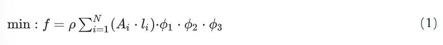
with design variables define

Where N is the total number of elements in the truss, with different values based on the truss typology selected by the optimiser at each iteration; ρ is the mass density of structural steel S235 (EN10025–2, European Code), equal to 7850 kg / m3, Ai is the area of the i-th member, is the length of the i-th member. Vector x collects the problem’s generic design variable (DV) of the problem, categorised into three different optimisation levels (size, shape, and topology). According to the specific case study, the DV’s vector will be expanded with a detailed description of each component and their influence in the OF will be described.
The penalty functions are Ф1 and Фj defined as:
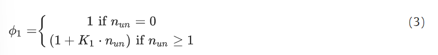
where K1 is a proportional constant nun the number of unfeasible individuals. Specifically, Ф1 is the penalty function associated with the structural safety of the structure. Eq. 3 displays a linear relationship that is directly proportional to the number of unfeasible individuals (nun) at each iteration. In this way, not only the level of violation but also the cardinality of the unfeasible elements has been considered.
The number of unfeasible elements nun is estimated by evaluating the following design inequalities based on European regulation. Specifically, Eq.s 4 and 5, concerning the combined bending and axial force as well as buckling verification under flexure and axial compression, has been implemented according to EC3 6.3.3., respectively. These verifications have been conducted with specific regard to columns and roof beams (i.e. purlins) within case study No. 2:
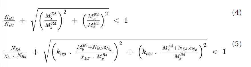
while, for truss elements only (i.e. case study No.1), structural checks under pure compression and tension axial forces have been implemented according to EC3 6.3.3.:
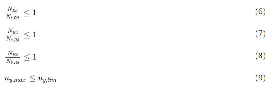
Where NEd is the design axial force, Nt,Rd and Nc,Rd and Nb,Rd are the tensile, compression and buckling capacity of the generic truss element, respectively. According to the type of section (i.e. circular hollow section) and grade of steel, class of section equal to 3 and buckling curve c have been adopted coherently with EC3 6.3.1.2 Table 6.2. In eq. 9, uy,max is the design deflection of the truss, while uy,lim is the limit deflection value. The latter, in the case of steel civil building, is assumed to be equal to L /200, with L being the total span of the truss beam coherently to the suggestion provided by Italian standard regulation.
The remaining penalty function Фj is defined as:
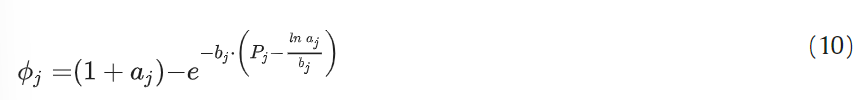
where aj, and bj are constants while Pj represents the constructability index and it is devoted to simulating the structural complexity during the construction process.
In this work, Pj is expressed by two distinct parameters as Na and n which represent the number of different cross-sections and the number of sub-divisions in the truss, respectively. Hence, the Фj penalty can be particularised as two distinct penalties ФNa and Фn .
In contrast to penalty Ф1, Фj (or ФNa and Фn penalties if explicitly declared) takes on an exponential form with a damping effect governed by negative exponential coefficients. Eq. 3 guides the algorithm to assign feasible sections for each class of elements that satisfy the structural verification and serviceability conditions outlined in Eqs. 6, 7, 8, and Eq. 9, respectively. On the other hand, Eq. 10 primarily aims to reduce the overall construction complexity by managing the number of different sections, Na , and the total number of pieces, n, employed for the truss layout definition.

2.2. Design Variables
The design variables are grouped after the optimisation goals, size, shape and topology. After establishing the general truss layout selected by the optimiser randomly, the structure’s sizing was determined by allocating predefined sections to each group of elements following the evolutionary criteria of SPEA-II. This choice aligns with practical recommendations and facilitates assembly. The main shape and topology variables are represented and the lower and upper bounds are collected where practical recommendations derived from the experience have been adopted.
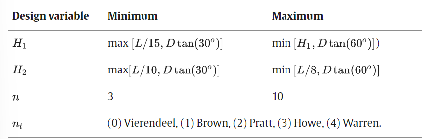
Main design variables considered for the truss optimisation
The shape optimisation variables include the number of subdivisions of half the chords (n), as well as the heights at the edges (H1) and the midpoint (H2) of the upper chord. To define the permissible range for n it was constrained to values between 3 and 10. The upper bound was determined with a minimum distance of 1 m between consecutive nodes. The span length of the truss was assumed to be equal to 20 m. The selection of the boundaries in Table 1 follows.
Topology optimisation involves selecting from five truss typologies through the discrete variable nt ∈{0, 1, 2, 3, 4}: (0) Vierendeel, (1) Brown, (2) Pratt, (3) Howe, and (4) Warren. These truss types are chosen based on their suitability for various engineering challenges and applications, making them valuable options in structural design.
Vierendeel Truss: Lacks diagonal members and has vertical struts in tension, requiring fully-restrained joints for stability under horizontal loads. Known for its aesthetic appeal in civil structures.
Brown Truss: Features X-shaped diagonals with one member always in tension, suitable for structures experiencing reversible loads, like wind or seismic actions, despite being heavier.
Howe Truss: Symmetrical compressed diagonals, ideal for uplift conditions in open buildings such as aircraft hangars.
Pratt Truss: Combines compressed and tensioned diagonals, capable of spanning 20 to 100 m, effective for horizontal loads.
Warren Truss: Upper chord in compression and lower chord in tension with alternating vertical elements to handle long spans, widely used in steel railway bridges.
These trusses are chosen for their adaptability to different structural demands and optimisation in design.
2.3. Grouping strategy
A two-level grouping strategy has been devised to highlight the engineering solutions achieved through the optimisation process, starting from the preliminary design phase. The fundamental concept is to gather elements with similar mechanical properties, such as compression or tension and stress levels. This approach guides the algorithm towards minimising structural complexity and overall cost. Employing different sections for every member in practical structural design is often impractical. Additionally, the assembly and erection processes favour installing entire truss sections at once. Consequently, organising elements into groups with shared mechanical characteristics results in more feasible engineering solutions.
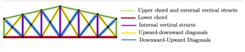 First-level grouping strategy of a brown truss
After obtaining the initial grouping of elements, a second-level classification has been established, considering the actual stress levels within each group of elements. Within each selected truss component, every member has been categorised into one of three primary classes based on the stress level experienced by the structure.
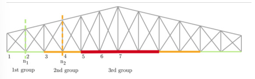 Second-level grouping strategy of the lower chord of a Brown truss based on the stress level
Case no. 1: 2D Steel Truss
The first case study is a planar truss with a span length of 20 m. The 2D modelling of each truss typology has been conducted aiming to reproduce the only axial (e.g. tension/compression) behaviour of bars except the Vierendeel truss for which fully-restrained joints have been considered. Simply-supported static scheme has been assumed for each truss system.
3.1. Load Definition and Design Variables
The gravitational loads are modelled following the Ultimate Limit State (ULS) combinations specified by the European Standard Regulation (EN 1993-1-1):

Here, G1, G2, and Qki represent the permanent structural loads, permanent non-structural loads, and variable loads, respectively. The coefficients γ are the partial safety factors determined based on the type of loads involved. The authors opted for the most critical scenario. In alignment with the practical application of this structure, an aluminium corrugated sheet was employed for the roof covering. All these forces were applied as concentrated loads at the upper nodes of each truss under investigation.
The calculated load values, along with their respective amplification factors, are summarised in the table below:
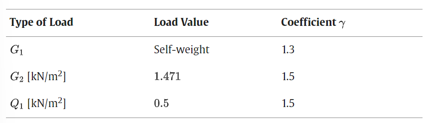 Vertical loads applied to the truss structure
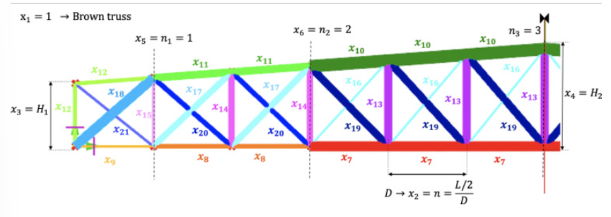 Schematic representation of all the design variables
3.2. Penalty Functions
In an optimisation process based on a penalty approach, the definition and calibration of penalty functions play a crucial role in achieving successful and feasible solutions.
Following the mathematical definition of the constructability penalty Фj, expressed by Eq. 10, it can be particularised as follows:
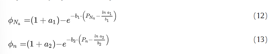
where a1 and b1 as well as a2 and b2 are the parameters that govern the final shape of the penalty functions ФNa and Фn coherently with the final constructability target represented by the number of different sections, Na , and the total number of pieces, n, respectively.
Especially for these penalties, It is worth noting that their geometric nature significantly affects the optimal design. In other words, the parameters tuning is not only vital to ensure convergence but also guides the algorithm towards preferring solutions with a higher or lower number of pieces and different sections, respectively. In this way, the parameters’ tuning of penalties does not affect the algorithm’s searching ability. On the other hand, it represents a crucial step to assess the proper level of penalisation achieving the preferable solution as a balance between total weight and structural complexity. This balance can be achieved according to the sensibility of the designer or the practical needs in the yard.
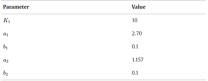
Penalties parameters
For K1, size optimisation was conducted on a brown truss with n = 6 elements, revealing no significant difference with higher K1 values. Hence, K1 = 10 was chosen.
Penalty functions Ф1 and Ф2 were adjusted, with ФNa’s parameters a1 and b1 affecting the penalty curve. Calibration started with b1 to set the trend, then a1 was adjusted for the desired penalty level.
When optimising for minimum weight using ФNa, the solution with the fewest cross-sections used b1 = 0.1. Although this approach reduced cross-sectional variety, it increased total weight due to constructability trade-offs. The optimiser consistently selected the same number of cross-sections, showing little sensitivity to varying penalty levels, with significant penalisation noticeable at higher Na values.
3.3. Results
The primary challenge is the high dispersion of results due to the large number of design variables and the complexity of the objective function (OF). Despite this dispersion, the differences in structural weights are negligible, with only a 0.023-ton difference between the best OF and the average weight across all OFs.
Larger sections are allocated from the edges to the middle span of the truss, matching the increasing stress levels. Conversely, for the diagonals and vertical struts, larger sections are assigned to all Group 2 and Group 3 members. The grouping strategy effectively reduces the number of different cross-sections by assigning identical sections to various truss components, significantly simplifying the structure.
4. Case no.2: 3D steel structure
A real-world case study has been considered to validate the proposed approach, encompassing all the constructability aspects discussed in previous sections. The building under investigation is located in the industrial area of “Mirafiori” in the South-West zone of Turin, Italy. The building represents a disused area that once housed activities of the famous FIAT company which was built in the early 60’s. It was built entirely by steel trussed frames supported by steel coupled sections and a roof realised by corrugated sheets.
As in the previous case study, the optimisation aims to minimise structural complexity. This complexity is gauged by considering the total number of components utilised in construction and the diversity of cross-sectional profiles employed.
4.1. Parametric modelling and load definition
The structure’s 3D model uses trusses for the roof and beam elements for columns and purlins, with elastic hinges connecting trusses to columns. Roof and vertical bracings are modeled as tension-only elements. The number of nodes and elements varies with truss type and module spacing.
Steel members are designed for axial stress, except for basement columns and rigidly connected bracings. Columns are fixed at 5 m with hinge joints for stability. The final design used an inertial equivalence procedure due to Karamba3D’s limitations, with the structure fixed at 60 m length and variable module spacing.
The analysis includes vertical loads: Permanent Structural Load (G1), Permanent Non-Structural Load (0.05 kN/m²), Maintenance Load (0.4 kN/m²), and Snow Load (1.23 kN/m²). Lateral loads are primarily Wind Load (pw), which varies with wind conditions affecting building facades and roof. Wind action values are detailed for each surface.
4.2. Definition of the design variables
The optimisation process applied to the industrial building follows the same objective function (Eq. 1) employed for the truss beams. Additionally, the same penalty approach utilising three different penalties, Ф1, Ф2, and Ф3, has been implemented. In this adaptation, the concept of the number of sections (Na) and the total number of pieces (Ntot) to encompass the new Design Variables (DVs) has been extended. Specifically, when calculating the value of Ntot, all elements comprising the entire structure have been considered, including the number of truss subdivisions (n) of the lower or upper chord halves (e.g. exploiting symmetry) for each truss beam within every frame and the total number of columns (Ncol).
Moreover, six additional DVs have been integrated, encompassing column, purlin, horizontal bracing (roof) cross-sections, and two vertical bracings (facade) types. These new DVs complement the ones defined in the previous case study, as shown in Table 4. Furthermore, a shape-related DV has been introduced, the number of modules (Nm), which pertains to half of the structure’s spatial configuration.
Shape optimisation at the industrial building level involves solely manipulating the number of modules, resulting in the removal or addition of trussed frames to the entire structure.
4.3. Results
The industrial building’s optimisation uses the same objective function and penalty approach (Ф1, Ф2, Ф3) as the truss beams. The calculation of total elements (Ntot) now includes all structural elements, truss subdivisions, and columns. Six new design variables (DVs) are added for column, purlin, and bracing cross-sections, along with a shape-related DV for the number of modules (Nm). Shape optimisation adjusts the number of modules, thereby adding or removing trussed frames from the structure.
5. Conclusions
In conclusion, the proposed optimisation approach, driven by penalty functions and adaptive cross-section assignments, offers a robust and flexible framework for designing steel structures. The successful application to truss beams and industrial buildings demonstrates its versatility and efficiency in managing complexity, reducing weight, and ensuring structural integrity. This research contributes to advancing structural optimisation methods, with practical implications for cost-effective and sustainable construction practices in various engineering applications. Further developments of the work will explore additional complexities and real-world constraints to refine and expand the applicability of this approach in structural engineering and design. Specifically, structural complexity will be investigated at the level of the connections of critical infrastructures (i.e. steel or steel-concrete composite bridge) where the standardisation of structural joints plays a crucial role, leading to significant time and economic cost savings because of the simplification at the design and construction processes.
Contributed By
Raffaele Cucuzza, Department of Structural, Geotechnical and Building Engineering, Politecnico di Torino, Turin, Italy
Majid Movahedi Rad, Department of Structural and Geotechnical Engineering, Széchenyi István University, Győr, Hungary


